Add-ons
Introduction
Add-ons are Docker containers that run on the same system as the operational layer.
The SystemManager process maintains the add-ons and can start, stop, and update the add-on at request.
The add-ons in the system are configured using the system add-on web app in a JSON editor, using the Docker Engine API (1.46) syntax.
Python package
A python package supports new python-addons. The package provides the interaction with the operational layer including:
ARTOF Redis interface interaction
Field manipulation
Platform configuration access
You can find the source code of the python package in the artof-utils project.
System add-on
The system add-on is implemented in python-Django and provides a web application to configure the robot. By default, the web application is hosted at port 80 on the computer running the add-on. Switch the App and Admin area in the upper right corner.
App area
Field
The Field Tab is the first tab you see when browsing the web application. This tab gives an overview of the available Fields in the system.
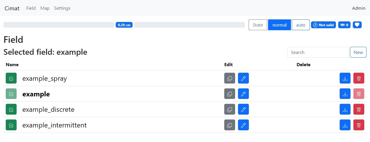
Figure 1. Tab App: Field
Select another field by pressing the button.
Duplicate a field using the grey button.
Edit a field by clicking on the button.
Download a field by pressing the button.
Delete a field by clicking on the button.
New field
To create a trajectory, geofence or task, you can select the following:
originalyou maintain the trajectory allocated to this field (only applicable when editing a field)fileyou can upload the shapefile of a Linestring.drawyou can draw the Linestring using the tools on the map.driveyou can drive in the AB line in the Tab Map.
Note
When you upload a shape file, you must upload the files with the extensions cpg, dbf, prj, shp and shx.
So, five files are selected in total.
Note
Always click on the button when performing a change. When the change is successful, the section folds in and highlights green; otherwise, the results are not saved.
When you’re done, click the Done button to return to the Tab Field.
Change the field name
Newto your desired field name and press the check icon button (Figure 2)Create a trajectory
Create geofence
Add one or more tasks (Figure 3)
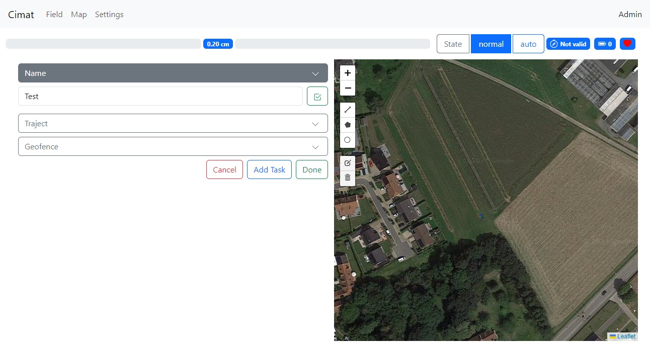
Figure 2. Tab App: Edit Field (alter the name)
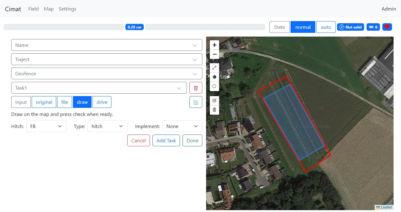
Figure 3. Tab App: Edit Field (optionally add a task)
Map
The Map gives an overview of the robot during operation.
On the map you can see:
The robot: blue rectangle
The hitch hinges and hitch pens: white dots
Hitch hinges become red when a hitch task activates the hitch.
The sections: white rectangles
The sections become red when activated by a continuous, discrete or intermittent task.
The green dots are visualizations of the navigation algorithm, including the robot reference, the closest point on the trajectory, and the look-ahead point.
The geofence: red polygon
The traject: red line with direction arrows
The tasks: green, blue, …, depending on the task type
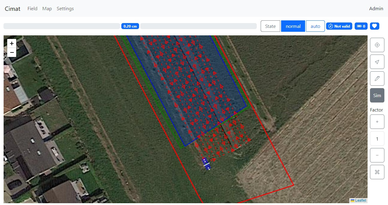
Figure 4. Tab App: Map
The right sidebar contains additional tools.
The button always places the robot in the center of the map.
The button toggles the north direction of the map.
The button opens the field edit tools (Figure 5).
With the first item selector, you can select every field layer (traject, geofence, task 1, task 2, etc.).
For a
trajecttheRow selected in the
Rowstext field can be extended, shifted or deleted.Rows can be added at the beginning or end of the trajectory.
With the
Drive inbutton you can drive in a new AB line. Not that this overwrites the previous trajectory.
For a polygon line shape such as a geofence or continuous task the polygon can be buffered
The
Simbutton activates simulation mode. When the operational layer communicates mechatronic layer, the robots go in Hardware In The Loop (HIL) testing; if not, you perform an integration test in the operational layer.With the simulation
Factor, you can multiply the simulation speed.The button at the bottom allows you to position the robot with a left mouse click. After that, you can also navigate the robot in simulation mode using the arrows on the keyboard. This is, of course, independent of the mechatronic layer and the behaviour of the attached physical robot.
Note
When performing changes with the tools, a preview of the changes is visualized in black on the map. Press the button to confirm your change and the button to upload it to the robot.
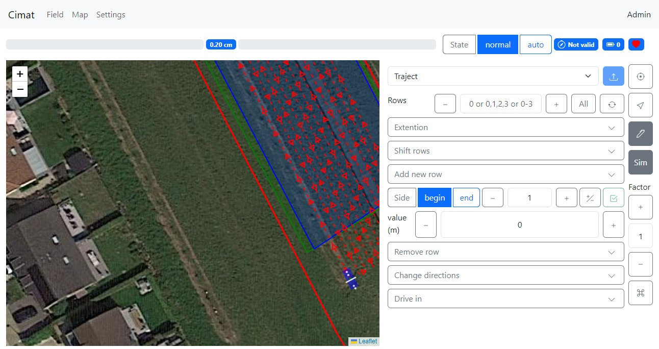
Figure 5. Tab App: Map Edit
Settings
The Settings are used to configure the operational functionality of the robot platform. You can configure
the navigation mode, as explained in Platform.
the operational and non-operational velocity. The robot uses the operational velocity when it is in a task polygon; otherwise, it uses the non-operational velocity.
the hitch height, and if provided by the robot’s hardware, the
floatmode.Navigation controller parameters.
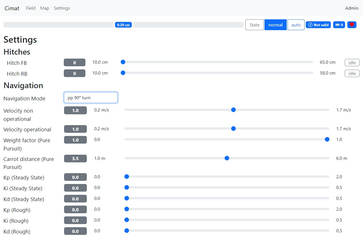
Figure 6. Tab App: Settings
Admin area
Settings
In the admin Settings, the configuration files can be edited with a JSON editor by pressing the button. After editing, press the Format button to check syntax errors and submit the changes with the button.
Note
Changes in the admin Settings require a restart of the robot (computer).
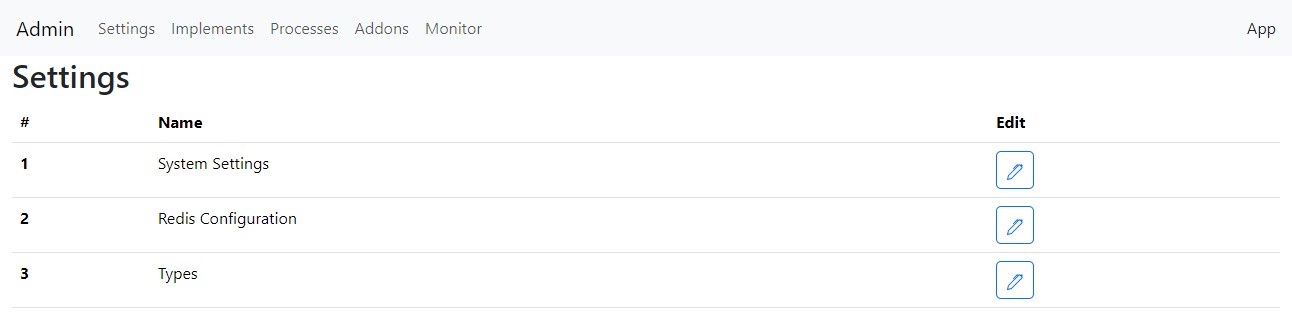
Figure 6. Tab Admin: Settings
Implements
You can add, remove or alter implements with the JSON editor.
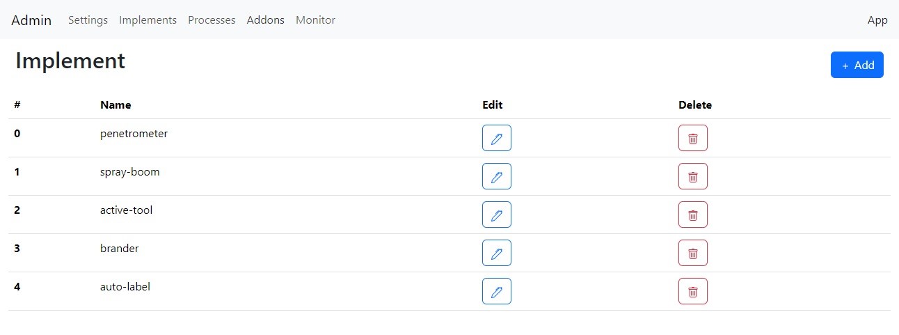
Figure 6. Tab Admin: Implements
Add a new implement using the button.
Remove an implement by pressing the button.
Alter an implement by pressing the button.
Note
When you are modifying an enabled implement in the selected field, you first need to toggle another field for the changes to occur.
Processes
The Process Tab lists information on the processes like starting time, state, etc.
Figure 7. Tab Admin: Implements
Start the process by pressing the button.
Stop the process by pressing the button.
You can see the process configuration by pressing the button (you cannot edit a process, so the submit button is disabled).
Add-ons
The Add-on Tab lists basic information about add-ons in the system, such as their starting time and status.
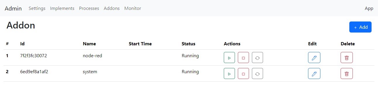
Figure 8. Tab Admin: Add-ons
Add a new add-on using the button.
Start the add-on by pressing the button.
Stop the add-on by pressing the button.
Update the add-on by pressing the button. The latest docker version of the add-on online available is pulled and installed.
Edit the add-on by pressing the button.
Delete the add-on by pressing the button.
Note
The add-on configuration uses the Docker Engine API (1.46) syntax.
Monitor
Except for JSON variables, you can monitor all Redis variables in the Monitor Tab on the system.
Use the search bar to find a specific variable.
Modify values by editing the new value in the Edit text field and press the for the change to occur.
Note
Altering plc.monitor does not have any effect, as it is immediately updated again by the PlcVariableManager.
Node-red add-on
The node-red add-on can be reached at the URL http://robotframework:1880/. Change “robotframework” to the robot’s IP address.
You can install the submodules for extracting the Redis variables and logging them to an InfluxDB instance by
<Coming soon>